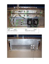
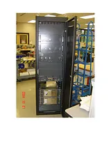
ユーザーズマニュアル目次Introduction11.1 Record of Revisions11.2 References11.3 General Safety Information21.4 Repair and Technical Support32.1 MC-Series System Configuration72.2 RadioFrame Networks Hardware92.3 System Manager Software242.4 Non-RFN Hardware252.5 Specifications273.1 Site Planning333.2 Scheduling / Logistics363.3 MC-Series System Installation Kit363.4 iDEN Configuration374.1 Site Inspection384.2 Receipt of Equipment384.3 Mounting the MC-Series System Cabinet394.4 Mounting Non-RFN Equipment in the MC-Series System Cabinet394.5 Mounting Auxiliary Equipment434.6 Cabinet-to-Site Cabling434.7 Intra-cabinet Cabling465.1 Prerequisites475.2 Checkout Procedures485.3 Initial Powering Procedure485.4 System Setup505.5 Connect the MC-Series System to the Third-party RF Distribution System555.6 Functionality Test556.1 Unsupported Datafill Parameters576.2 Parameters that Do Not Apply to the MC-Series System586.3 Recommended Datafill Parameters586.4 MIB Disparity616.5 Local Performance Monitoring62Scheduled and Unscheduled Maintenance647.1 Annual Maintenance647.2 Troubleshooting Guidelines647.3 Fault Indications647.4 System Manager Alarms687.5 RF Shelf Alarms and Test Ports877.6 RadioBlade Alarm Handling897.7 Serial Log Upload Procedure917.8 Power Down Procedure927.9 Field Replaceable Unit (FRU) Procedures937.10 TOR Tx Measurement Procedure112System Configuration Changes1138.1 Upgrading MC-Series System Software1138.2 Adding or Removing RadioBlades1188.3 Adding a Sector1188.4 Removing a Sector1208.5 Parts and Suppliers1228.6 Available Field Replaceable Units (FRUs)1238.7 Spares124A. Glossary125B. Default IP Addresses127C. Cabling Diagrams: 3-Sector Configuration128D. Cabling Diagrams: Omni Configuration134E. Tx / Rx Curves140F. Functionality Test Procedures142G. System Manager148H. BER Test Procedure156The MC-Series System cabinet6MC-Series System 3-sector configuration8MC-Series System functional diagram9BIC front view10BIC rear view10BIC CRIC ports and indicators10BPC indicators11ERTM ports and indicators11CRTC ports and indicators11AIC front view13AIC rear view13AIC CRIC ports and indicators14BPC+SPAM indicators14ERTM ports and indicators14RBS group functional diagram16RBS interior, top down view17RBS front view17RBS rear view18iDEN 2-port RadioBlade transceiver19RF Shelf functional diagram20RF Shelf front view21RF Shelf rear view21PDU front view23PDU rear view23Punch block location within the MC-Series rack.26MC-Series System rack locations for non-RFN hardware40Top of the rack (TOR) cabling and equipment44RadioBlade fault Bounce and Duration for alarm generation.90RF Shelf front view94RF Shelf rear view94Front view of BIC98Front view of AIC99Front view of RBS101Replacing the CRIC in the BIC or AIC.103Replacing the BPC in the BIC or the BPC+SPAM in the AIC.104Rear of BIC (ERTM and CRTC) and AIC (ERTM only).106Front view of the RadioBlade Shelf (RBS)108PDU Rear view111PDU rear view111MC-Series System Omni Configuration134Transmit filter frequency response140Receive filter frequency response141MC-Series System FRUs4PDU Circuit Breaker Overview23TOR output power is based on the DefaultTxPower and the Attenuator setting59Alarm Interface Port Pinout87RF Shelf Diagnostic Port Pinout88MC-Series System FRUs93MC-Series System FRUs123Interconnect Call Quality, Setup and Stability142Group Dispatch Call Quality, Setup, and Stability142Private Dispatch Call Quality, Setup, and Stability143Packet Data Latency over the MC-Series System (Ping –n 100 –w 2000 xx.xxx144Packet Data Latency over Motorola EBTS144Handover & Idle Mode Reselection145Interconnect Connection Stability145Dispatch Connection Stability145サイズ: 3.48MBページ数: 167Language: Englishマニュアルを開く