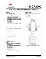
数据表目录MCP2200 - USB 2.0 to UART Protocol Converter with GPIO1Block Diagram21.0 Functional Description3TABLE 1-1: Pinout Description31.1 Supported Operating Systems41.2 Control Module41.3 UART Interface4TABLE 1-2: UART Configurations4TABLE 1-3: UART Primary Baud Rates4FIGURE 1-1: RTS/CTS Connections Example51.4 USB Protocol Controller51.5 USB Transceiver5FIGURE 1-2: MCP2200 Internal Power Supply Details6FIGURE 1-3: Bus Power Only6FIGURE 1-4: Typical Power Supply Option Using the 5V Provided by the USB7FIGURE 1-5: Using an Externally Provided 3.3V Power Supply71.6 GPIO Module71.7 EEPROM Module81.8 RESET/POR81.9 Oscillator8FIGURE 1-6: Quartz Crystal Operation8FIGURE 1-7: Ceramic Resonator Operation82.0 Configuration92.1 Configuration Utility92.2 Serial String9TABLE 2-1: Configuration Descriptions9FIGURE 2-1: Configuration Utility102.3 Simple Configuration and I/O DLL11TABLE 2-2: Configuration Functions113.0 Electrical Characteristics253.1 DC Characteristics26FIGURE 3-1: POR and POR Rearm with Slow Rising Vdd27TABLE 3-1: USB Module Specifications27TABLE 3-2: Thermal Considerations283.2 AC Characteristics29TABLE 3-3: Temperature and Voltage Specifications - AC29FIGURE 3-2: Load Conditions for device Timing Specifications29TABLE 3-4: Reset, Oscillator Start-up Timer and Power-up Timer Parameters304.0 Packaging Information31Appendix A: Revision History39Product Identification System41Worldwide Sales and Service44文件大小: 504.0 KB页数: 44Language: English打开用户手册
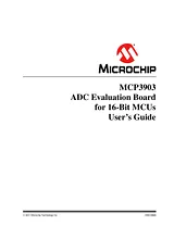
用户手册目录Trademarks2Preface5Introduction5Document Layout5Conventions Used in this Guide6Recommended Reading7The Microchip Web Site7Customer Support7Document Revision History7Chapter 1. Hardware Description91.1 Overview91.2 PIM Module / MCP3903 Connection and Peripheral Usage Overview111.3 Analog Input Structure131.4 USB to Serial Converter13Chapter 2. Code Example152.1 dsPIC33 Example Description15Appendix A. Schematics and Layouts19A.1 Introduction19A.2 Schematic - Analog20A.3 Schematic - LCD and UART21A.4 Schematic - USB and Memory22A.5 Schematic - Microcontroller (MCU)23A.6 Schematic - PIM Module24A.7 Schematic - Power25A.8 Board - Top Trace and Top Silk26A.9 Board - Bottom Trace and Bottom Silk26A.10 Board - Layer #2 VDD27A.11 Board - Layer #3 GND27A.12 Board - Top SILK and PADS28A.13 Board - Bottom SILK and PADS28Appendix B. Bill of Materials (BOM)29Worldwide Sales and Service32文件大小: 1.4 MB页数: 32Language: English打开用户手册
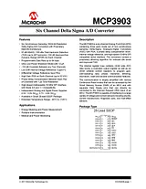
数据表目录1.0 Electrical Characteristics31.1 Reliability Targets31.2 serial interface characteristics6FIGURE 1-1: Serial Output Timing Diagram.7FIGURE 1-2: Serial Input Timing Diagram.7FIGURE 1-3: Data Ready Pulse Timing Diagram.8FIGURE 1-4: Specific Timing Diagrams.8FIGURE 1-5: MCP3903 Clock Detail.82.0 Typical Performance Curves9FIGURE 2-1: Spectral Response.9FIGURE 2-2: Spectral Response.9FIGURE 2-3: Spectral Response.9FIGURE 2-4: Spectral Response.9FIGURE 2-5: Spectral Response.9FIGURE 2-6: Spectral Response.9FIGURE 2-7: Spectral Response.10FIGURE 2-8: Spurious Free Dynamic Range vs Oversampling Ratio.10FIGURE 2-9: Signal-to-Noise and Distortion vs. Oversampling Ratio.10FIGURE 2-10: Signal-to-Noise and Distortion vs. Gain (Dithering OFF).10FIGURE 2-11: Signal-to-Noise and Distortion vs. Gain (Dithering ON).10FIGURE 2-12: Total Harmonic Distortion vs. Oversampling Ratio.10FIGURE 2-13: Total Harmonic Distortion vs. Input Signal Frequency.11FIGURE 2-14: Total Harmonic Distortion vs. Temperature.11FIGURE 2-15: Signal-to-Noise and Distortion vs. Input Signal Frequency.11FIGURE 2-16: Signal-to-Noise and Distortion vs. Temperature.11FIGURE 2-17: Signal-to-Noise and Distortion vs. Input Signal Amplitude.11FIGURE 2-18: Signal-to-Noise and Distortion vs. Master Clock.11FIGURE 2-19: Offset Error vs. Temperature (Channel 0).12FIGURE 2-20: Channel-to-Channel Offset Match vs. Temperature.12FIGURE 2-21: Gain Error vs. Temperature.12FIGURE 2-22: Internal Voltage Reference vs. Temperature.12FIGURE 2-23: Internal Voltage Reference vs. Supply Voltage.12FIGURE 2-24: Noise Histogram.12FIGURE 2-25: Integral Non-Linearity (Dithering OFF).13FIGURE 2-26: Integral Non-Linearity (Dithering ON).13FIGURE 2-27: Operating Current vs. Master Clock (MCLK).133.0 Pin Description14TABLE 3-1: Pin Function Table143.1 RESET143.2 Digital VDD (DVDD)143.3 Analog VDD (AVDD)153.4 ADC Differential Analog Inputs(CHn+/CHn-)153.5 Analog Ground (AGND)153.6 Non-Inverting Reference Input, Internal Reference Output (REFIN+/OUT)153.7 Inverting Reference Input (REFIN-)153.8 Digital Ground Connection (DGND)153.9 DRn (Data Ready Pins)153.10 Oscillator And Master Clock Input Pins (OSC1/CLKI, OSC2)163.11 CS (Chip Select)163.12 SCK (Serial Data Clock)163.13 SDO (Serial Data Output)163.14 SDI (Serial Data Input)164.0 Terminology And Formulas174.1 MCLK - Master Clock174.2 AMCLK - Analog Master Clock17TABLE 4-1: MCP3903 OVERSAMPLING RATIO SETTINGS174.3 DMCLK - Digital Master Clock174.4 DRCLK - Data Rate Clock17TABLE 4-2: Device data rates in function of mclk, osr, AND PRESCALE184.5 OSR - Oversampling Ratio18TABLE 4-3: MCP3903 OVERSAMPLING RATIO SETTINGS184.6 Offset Error184.7 Gain Error184.8 Integral Non-Linearity Error194.9 Signal-To-Noise Ratio (SNR)194.10 Signal-To-Noise Ratio And Distortion (SINAD)194.11 Total Harmonic Distortion (THD)194.12 Spurious-Free Dynamic Range (SFDR)194.13 MCP3903 Delta-Sigma Architecture204.14 Idle Tones204.15 Dithering204.16 Crosstalk214.17 PSRR214.18 CMRR214.19 ADC Reset Mode214.20 Hard Reset Mode (RESET = 0)224.21 ADC Shutdown Mode224.22 Full Shutdown Mode225.0 Device Overview235.1 Analog Inputs (CHn+/-)235.2 Programmable Gain Amplifiers (PGA)23TABLE 5-1: pga configuration Setting235.3 Delta-Sigma Modulator23FIGURE 5-1: Simplified Delta-Sigma ADC Block Diagram.235.4 SINC3 Filter25TABLE 5-2: adc RESOLUTION vs. osr25FIGURE 5-2: SINC Filter Response with MCLK = 4 MHz, OSR = 64, PRESCALE = 1.255.5 ADC OUTPUT CODING26TABLE 5-3: OSR = 256 output code examples26TABLE 5-4: OSR = 128 output code examples26TABLE 5-5: OSR = 64 output code examples27TABLE 5-6: OSR = 32 output code examples275.6 Voltage Reference275.7 Power-on Reset28FIGURE 5-3: Power-on Reset Operation.285.8 RESET Effect On Delta Sigma Modulator/SINC Filter285.9 Phase Delay Block28TABLE 5-7: Phase Values With MCLK = 4 MHz, OSR = 256295.10 Crystal Oscillator296.0 Serial Interface description306.1 OVERVIEW306.2 CONTROL BYTE30FIGURE 6-1: Control Byte.306.3 Reading from the Device306.4 Writing to the Device306.5 SPI MODE 0,0 - Clock Idle Low, Read/Write Examples30FIGURE 6-2: Device Read (SPI MODE 0,0 - Clock Idles Low).31FIGURE 6-3: Device Write (SPI Mode 0,0 - Clock Idles Low).316.6 SPI MODE 1,1 - Clock Idle High, Read/Write Examples31FIGURE 6-4: Device Read (SPI Mode 1,1 - Clock Idles High).31FIGURE 6-5: Device Write (SPI Mode 1,1 - Clock Idles High).326.7 Read Continuously Channel Data, LOOPING ON ADDRESS SETS32FIGURE 6-6: Typical Continuous Read Communication.326.8 Situations that Reset ADC Data336.9 Line Cycle Sampling Options33TABLE 6-1: MCLK Frequencies for Line Sampling33FIGURE 6-7: Standard Device Operation.346.10 Data Ready Pulses (DRn)34FIGURE 6-8: Data Ready Behavior.356.11 Data Ready Pulse with Phase Delay36FIGURE 6-9: Internal Latches Synchronizing Data Ready Pulses with Phase Delay Present (Single Channel Pair Shown).367.0 Internal Registers37TABLE 7-1: Internal Register Summary37TABLE 7-2: Continuous Read Options, Looping on Internal Addresses377.1 Channel Output Registers37TABLE 7-3: ADC OUTPUT Registers377.2 Mod Register39TABLE 7-4: Modulator OUTPUT REGISTER397.3 Phase Register40TABLE 7-5: phase REGISTER407.4 Gain Configuration Register41TABLE 7-6: gain REGISTER417.5 STATUS/COM Register - Status and Communication Register42TABLE 7-7: STATUS/COM Register427.6 Config Register - Configuration Register44TABLE 7-8: CONFIG Register448.0 Packaging Information458.1 Package Marking Information45Corporate Office54Atlanta54Boston54Chicago54Cleveland54Fax: 216-447-064354Dallas54Detroit54Indianapolis54Toronto54Fax: 852-2401-343154Australia - Sydney54China - Beijing54China - Shanghai54India - Bangalore54Korea - Daegu54Korea - Seoul54Singapore54Taiwan - Taipei54Fax: 43-7242-2244-39354Denmark - Copenhagen54France - Paris54Germany - Munich54Italy - Milan54Spain - Madrid54UK - Wokingham54Worldwide Sales and Service54Trademarks53Worldwide Sales and Service54文件大小: 1.6 MB页数: 54Language: English打开用户手册