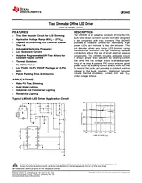
数据表 (LM3445-120VFLBK/NOPB)目录FEATURES1APPLICATIONS1DESCRIPTION1Typical LM3445 LED Driver Application Circuit1Connection Diagram2ABSOLUTE MAXIMUM RATINGS3OPERATING CONDITIONS3ELECTRICAL CHARACTERISTICS3TYPICAL PERFORMANCE CHARACTERISTICS5SIMPLIFIED INTERNAL BLOCK DIAGRAM7APPLICATION INFORMATION7FUNCTIONAL DESCRIPTION7OVERVIEW OF PHASE CONTROL DIMMING7THEORY OF OPERATION9SENSING THE RECTIFIED TRIAC WAVEFORM10LM3445 LINE SENSING CIRCUITRY10TRIAC HOLDING CURRENT RESISTOR11ANGLE DETECT12BLEEDER12FLTR1 PIN12DIM DECODER12VALLEY-FILL CIRCUIT13VALLEY-FILL OPERATION13BUCK CONVERTER14OVERVIEW OF CONSTANT OFF-TIME CONTROL15MASTER/SLAVE OPERATION16MASTER/SLAVE CONFIGURATION16MASTER BOARD MODIFICATIONS16SLAVE BOARD(S) MODIFICATIONS16MASTER/SLAVE(S) INTERCONNECTION16MASTER/SLAVE THEORY OF OPERATION16MASTER/SLAVE CONNECTION DIAGRAM17MASTER/SLAVE BLOCK DIAGRAMS18THERMAL SHUTDOWN19DESIGN GUIDE20DETERMINING DUTY-CYCLE (D)20CALCULATING OFF-TIME20SETTING THE SWITCHING FREQUENCY20INDUCTOR SELECTION21SETTING THE LED CURRENT23VALLEY FILL CAPACITORS23Determining the capacitance value of the valley-fill capacitors24Determining Maximum Number of Series Connected LEDs Allowed24OUTPUT CAPACITOR26SWITCHING MOSFET26RE-CIRCULATING DIODE27DESIGN EXAMPLE28LM3445 DESIGN EXAMPLE 1 INPUT = 90VAC TO 135VAC, VLED = 7 x HB LED STRING APPLICATION @ 400 MA30Revision History32文件大小: 1.1 MB页数: 39Language: English打开用户手册
用户手册 (LM3445-120VFLBK/NOPB)目录Introduction3Key Features3Applications3Performance Specifications3Demo Board4LED Current vs. Input Voltage (using Dimmer)4LM3445 120VAC, 8W Isolated Flyback LED Driver Demo Board Schematic5Demo Board Schematic6LM3445 Device Pin-Out7Bill of Materials7LM3445 Device Pin-Out7Pin Description 10 Pin VSSOP7Demo Board Wiring Overview9Wiring Connection Diagram9Wiring Connection9Demo Board Assembly10Top View10Bottom View10Typical Performance Characteristics11Efficiency vs. Line Voltage Original Circuit11Efficiency vs. Line Voltage Modified Circuits11LED Current vs. Line Voltage Original Circuit11LED Current vs. Line Voltage Modified Circuits11Power Factor vs. Line Voltage Original Circuit11Power Factor vs. Line Voltage Modified Circuits11Output Power vs. Line Voltage Original Circuit12Output Power vs. Line Voltage Modified Circuits12Power MOSFET Drain Voltage Waveform (VIN = 120VRMS, 6 LEDs, ILED = 350mA)12Current Sense Waveform (VIN = 120VRMS, 6 LEDs, ILED = 350mA)12FLTR2 Waveform (VIN = 120VRMS, 6 LEDs, ILED = 350mA)12PCB Layout14Top Layer14Bottom Layer14Transformer Design15Experimental Results1613.1 Non-Dimming Performance16Measured Efficiency and Line Regulation (6 LEDs, No TRIAC Dimmer)16TRIAC Dimmer)1613.2 Dimming Performance17Measured Efficiency and Line Regulation Data (with TRIAC Dimmer)17LED Current vs. Input Voltage (using Dimmer)1813.3 Power Factor Performance19Current Harmonic Performance vs. EN/IEC61000-3-2 Class C Limits19Circuit Operation With Rotary Forward Phase TRIAC Dimmer20Forward Phase Circuit at Full Brightness20Forward Phase Circuit at 90° Firing Angle20Forward Phase Circuit at 150° Firing Angle20Circuit Operation With Reverse Phase TRIAC Dimmer21Reverse Phase Circuit at Full Brightness21Reverse Phase Circuit at 90° Firing Angle21Reverse Phase Circuit at 150° Firing Angle21Electromagnetic Interference (EMI)22Input EMI Filter and Rectifier Circuit22Peak Conductive EMI Scan per CISPR-22, Class B Limits22Peak Conductive EMI Scan with Additional 33nF of Input Capacitance23Thermal Analysis24Top Side Thermal Scan24Bottom Side Thermal Scan25Circuit Analysis and Explanations2618.1 Injecting Line Voltage into Filter-2 (Achieving PFC > 0.95)26Line Voltage Injection Circuit26FLTR2 Waveform with No Dimmer26Typical Operation of FLTR2 Pin27文件大小: 24.0 MB页数: 28Language: English打开用户手册